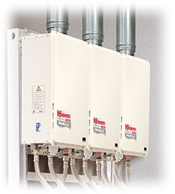
INDOOR INSTALLATION
The Rheem 27 CFWH is available in models suitable for indoor installation. The flue system is room sealed concentric design manufactured from high grade stainless steel inner and aluminised steel outer.
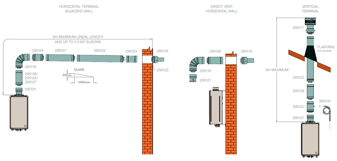
The flue system is certified for up to 9m lineal run and 3 x 90° bends and is suitable for vertical or horizontal termination when used with the appropriate terminal.
Separate ventilation for combustion is not required as the air for combustion is supplied in the flue outer. The flue system can be installed with zero clearances from combustible materials. Flue termination must comply with the requirements of AS5601.
WARNING:
Rheem indoor continuous flow water heaters must only be installed using certified Rheem coaxial flue components. Do not use any other type of flue parts. Carefully follow the Installation Instructions.
Typical Installations
How To Size
Use the following as a guide to selecting the flue components required. The installed dimension of each flue piece is shown in the drawings.
Determine the lineal distance and number of 45° and/or 90° bends between the top of the water heater and flue terminal. Note, the bottom edge of a vertical flue terminal must be 500mm away from the nearest structure in accordance with AS5601.
Flashing is required to be installed where a vertical flue section penetrates the roof line (not supplied).
Where a condensate drain section is installed, the hose must be connected and drained to the sewer waste or outside. A condensate trap must be installed and filled with water to prevent spillage of products of combustion.
Flue penetrations through walls and ceilings must be sealed in accordance with local fire regulations.
Download Continuous Flow Flue System - Installation Overview
RHEEM CONTINUOUS FLOW FLUE COMPONENTS
| DESCRIPTION | WHERE USED | |
|---|---|---|
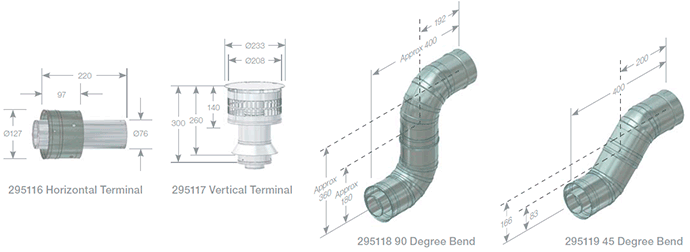
| 295116 | Horizontal Terminal | Required where flue terminates horizontally |
| 295117 | Vertical Terminal | Required where flue terminates vertically |
| 295118 | 90° Bend | Maximum of 3 per installation |
| 295119 | 45° Bend | Maximum of 6 per installation (with no 90° bends) |
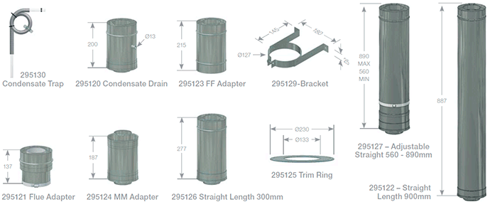
| 295120 | Condensate Drain | Can be located in vertical or horizontal section. Required for: - Vertically terminating flue systems - Horizontally terminating flue systems with vertical flue sections greater than 2m |
| 295121 | Water Heater/Flue Adapter | Required for each water heater to connect to flue system |
| 295122 | Straight Length 900mm | Long straight sections |
| 295123 | Female-Female Adapter | Required to reverse flue pipe direction to allow condensate to drain away correctly from water heater in long horizontal sections of horizontally terminating flues (greater than 2.7m) |
| 295124 | Male-Male Adapter | Required to reverse flue pipe direction to allow condensate to drain away correctly from water heater in long horizontal sections of horizontally terminating flues (greater than 2.7m) |
| 295125 | Trim Ring (optional) | Conceal internal and/or external hole in wall for horizontally terminating flues |
| 295126 | Straight Length 300mm | Short straight sections |
| 295127 | Adjustable Length 560-890mm | Allows to trim flue to exact length required |
| 295129 | Bracket | Support flue at intervals not exceeding 2m and after any bend |
| 295130 | Condensate Trap | Required with every condensate drain. Can be connected to a common waste |
MULTIPLE WATER HEATER FLUE INSTALLATION
Where multiple water heaters are installed, each water heater must be individually flued to the outside. A common flue system MUST NOT be used.
For a multiple unit installation, the water heater is certified for installation with zero clearance between adjacent water heaters. Observe flue terminal clearances from other objects in accordance with AS 5601.
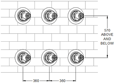
Horizontal Flue Terminations
- The minimum horizontal centre to centre distance between flue terminals is to be no less than 360 mm.
- The minimum vertical centre to centre distance between flue terminals is to be no less than 570 mm.
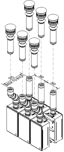
Vertical Flue Terminations
- The minimum side by side centre to centre distance between flue terminals is to be no less than 360 mm.
- The minimum back to back centre to centre distance between flue terminals is to be no less than 570 mm.
 site.
site.